In a previous article, I wrote about the role that simulation can play in the design and optimization of mining equipment. This time, I would like to continue with a discussion on the broader topic of simulation’s role in the natural resources sector. This article will pay special attention to oil and gas applications and the applicability of CAE software in this demanding industry.
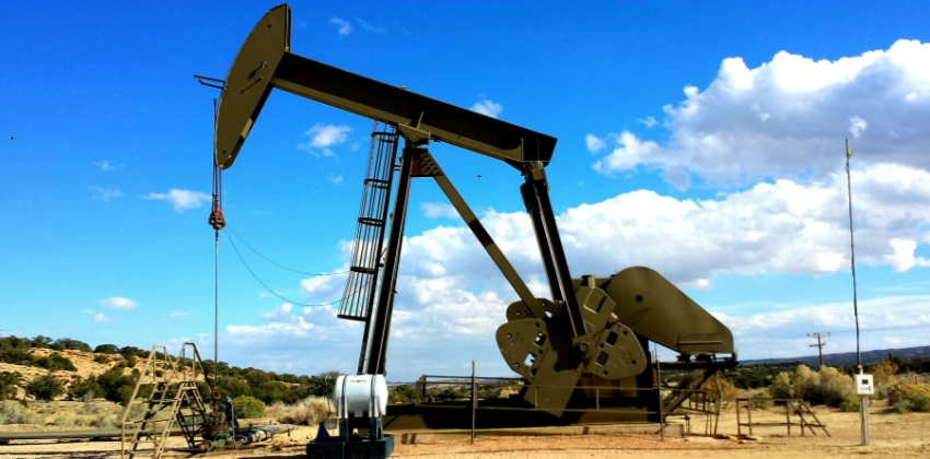
Oil and gas drilling requires a variety of equipment, such as the crown and crown block situated at the apex of the rig, traveling block, draw works, sand pipe, engine, fuel or water tanks, swivel, rotary hose, turntable, pipe rack, conductor pipe, borehole, bit, drill pipe, mud pit and mud pump.
But the drilling process in oil and gas extraction is already well understood. What is more interesting, however, is that the same drilling infrastructure can perform seismic surveys based on shock waves.
Generated by the drilling infrastructure, the shock waves travel to the heart of the earth and are reflected back to the surface by the different layers of rocks. The reflections travel at a varying speed depending on the density or category of the layers of rock through which they pass. The shock waves are reflected and picked up by the audio-sensitive vibration detectors or microphones. On land, the drilling parts consist of seismometers, while those on the water are done by the drilling hydrophones. In this way, the seismologists can interpret the anomalies associated with typical structures for gas or petroleum traps and oil.
To discover all the simulation features provided by SimScale, download the document below.
Simulation for Oil and Gas Industry
The typical simulation analyses used to improve the performance of oil and gas equipment are:
- Drilling columns – structural stress and dynamic stress, CFD, thermodynamic
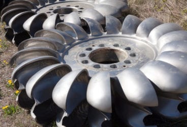
- Hydropower devices – structural and multiple CFD
- Pumps – structural, CFD, thermodynamic
- Pipes system (industrial water, petroleum) – structural stress and fluid dynamics
- Storage tanks (fuel tank, oil tank, pressure vessel, etc.) – structural pressure, fluid circulation
- Oil platforms – structural static and dynamic
On a more practical level, however, it is beneficial to observe relevant simulations in real examples. Here are some interesting projects for oil and gas from the SimScale Public Projects:
1. Wave Impact on an Oil Rig Platform
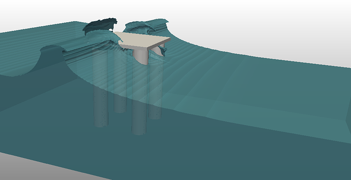
This project simulates the impact of sea waves against the columns of an oil rig. A scaled geometry that maintains the Froude number of the actual phenomenon is used. The geometry was meshed on the SimScale platform using the snappyHexMesh tool. The resulting mesh consists of approximately 8,500,000 volumes.
2. Thermal-Structural Analysis of a Pressure Vessel
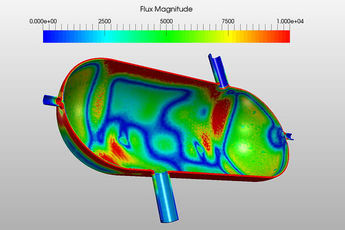
A very interesting simulation with applications in the extraction and preservation of underground excavation is this thermal-structural analysis of a pressure vessel. Pressure vessels are normally used for storing high-pressure liquid or gas. In this simulation, a copper pressure vessel was considered. It has a steel coating inside and contains hot water at a temperature of 593 K (290 °C), which was then cooled down by cold water at 293 K (25 °C).
For this analysis, transient thermostructural was selected because we understand that temperature is changed over time. Copper was selected as the vessel material, whereas steel was selected for the inner coating.
The material table was then uploaded, which contains the material parameters at different temperatures. The vessel has two pipes: an upper pipe for cold water inlet and a lower pipe for hot water outlet. Imaginary valves were considered between pipes and the vessel. The simulation results show the temperature, heat flux and stresses in pipes and vessel at 2020 seconds (33.75 minutes).
3. Sloshing of Fluid in a Moving Fuel Tank
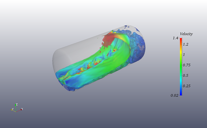
Additionally, an important project for petroleum storage is this simulation of sloshing fluid in a moving fuel tank. Movement of the fuel tank was assigned by the Solid Body Motion option for the tank. The geometry is a 30-gallon cylindrical tank. The inside domain was meshed using the SnappyHexMesh on the SimScale platform and has about 0.5 million cells.
For this sample project, the fluid is assigned properties of water and the second phase is air. The simulation was run on eight computer cores and took around 11 hours to complete.
All the projects presented in this article can be imported into your own workspace and used as templates. Feel free to browse the SimScale Public Projects for other interesting simulations.
To learn about engineering simulation in heavy machinery and agricultural equipment, watch this webinar recording.
