
Cost savings

Design iterations

Computing time per iteration
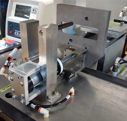
Cincinnati Test Systems is a leading designer and manufacturer of standard and custom leak test systems and leak detection equipment. Leak testing is critical to ensuring proper product quality, safety, and performance. CTS has been delivering precision leak detection equipment, function test systems, and assembly verification testing to manufacturers throughout the world since 1981. The company is known as the industry expert in virtually every major market, from automotive parts like castings, solenoid valves or high-pressure fuel system components, to the medical industry, ranging from catheters to surgical instruments.
Ensuring the integrity of critical system components is one of the most important factors in the manufacturing process of such products.
They have to remain reliably sealed for extended amounts of time (in many cases over 10 years), with allowed ingress or egress rates as low as 10-9 – 10-7 std.cm3/sec. These extremely stringent requirements call for precise testing. One of the most commonly used approaches is based on pressurising the test parts with helium and detecting the escaping gas with high sensitivity instruments (e.g., mass spectrometers).
Using mass spectrometers to detect very small leaks traditionally requires high vacuum around the component undergoing the test. This results in the need for vacuum pumps and precise mechanical components (vacuum chambers, tooling).
An alternative test method (so-called accumulation testing) does not require vacuum but measures the rate of concentration increase of helium or another trace gas in an isolated chamber surrounding the part undergoing the test. Although this method requires longer test times and is somewhat less sensitive, it can result in significant cost savings and is the method of choice when test times are not very critical and/or exposing the test part to vacuum is not desirable.
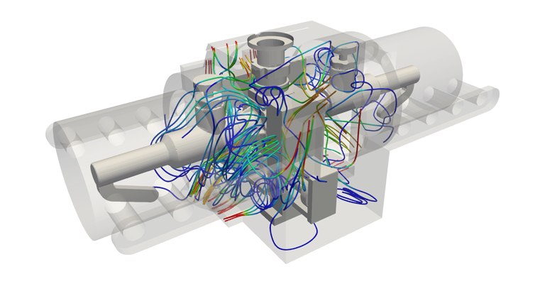
To enhance gas mixing in such systems, fans or blowers are used to agitate air surrounding the test part. This carries the danger of creating areas with low air flow — so-called “blind spots”. These can jeopardize test integrity because leaks in these areas of the test part may be detected with a significant delay or not at all within the available test time.
The access to highly powerful computing resources in a very easy-to-use environment makes SimScale the platform of choice for complex problems that would otherwise require significant investment in hardware and software. The services provided bring access to highly advanced simulation methods within reach for small and medium-sized businesses at a very affordable rate.

Peter Bonyhati
Systems Engineer, Cincinnati Test Systems
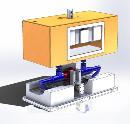
The first step of the analysis process involved CAD cleanup. Both the test part and the chamber are very complex objects with a significant amount of detail. Since the SimScale platform focuses on numerical simulations (and has very limited CAD cleanup capabilities) the geometry preparation had to be done using third-party software. After overcoming this modelling challenge, the analysis part was very straightforward.
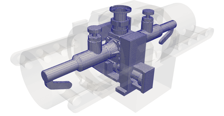
The clean CAD was first meshed with a Moderate Automatic Hex Mesher which resulted in 1.5 million cells. This discretized volume was used to calculate initial flow on 96 cores. The results were ready after only 20 minutes and provided a valuable insight into the general flow pattern. To ensure that all circulation features were captured, the second mesh using a Fine Automatic Hex Mesher was prepared.
The resulting case contained around 8 million volumes and needed approximately 2 hours on 96 cores to finish computing. After establishing a reliable workflow, two more geometry variants were tested, summing up to 4 configurations of steady state incompressible turbulent flow analysis.
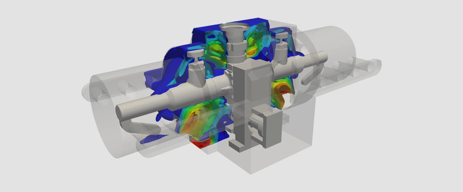
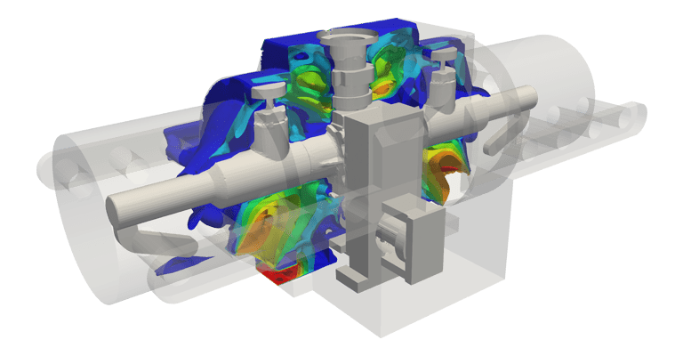
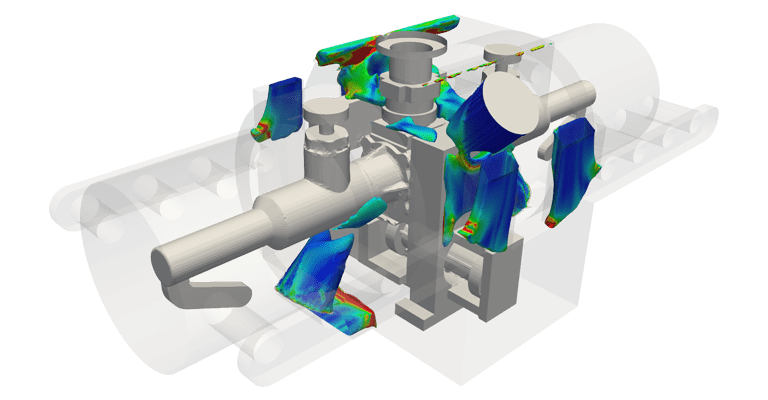
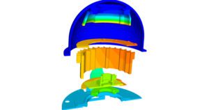
The geometry investigation revolved around two features of the measurement chamber: the location of the filler blocks and the position of the recirculation fans. A study of the original measurement setup revealed a dead zone in the gap between the tooling and the test part.
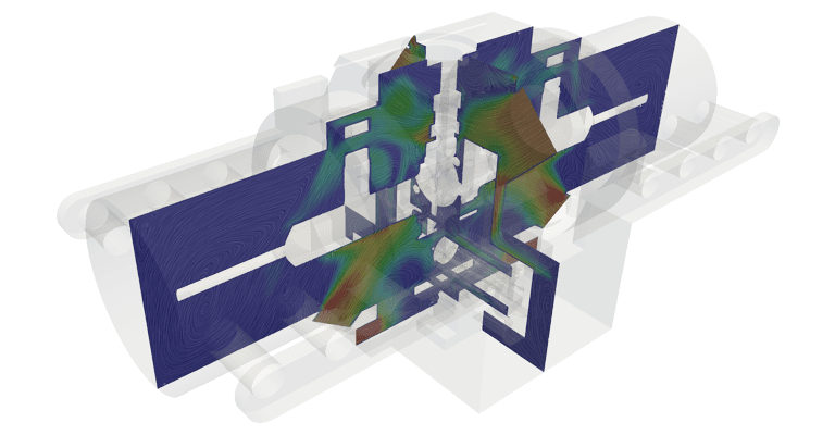
The elimination of this flow feature was of crucial importance. This was obtained by adding 2 more fans to the system and repositioning flow blockers. A significantly improved air pattern was obtained.
The application of CFD with SimScale allowed Cincinnati Test Systems to save around $10,000 for each one of the 4 design iterations. Considering that blind spots like the ones identified traditionally could only be identified by iterative physical testing that may take weeks, significant time savings were also possible.
Additionally, the ability to make improvements to the tooling in the design phase saved thousands of dollars in re-manufacturing costs.
“The application of CFD with SimScale allowed Cincinnati Test Systems to save around $10,000 for each one of the 4 design iterations, besides the savings in re-manufacturing costs.”


Sign up for SimScale
and start simulating now