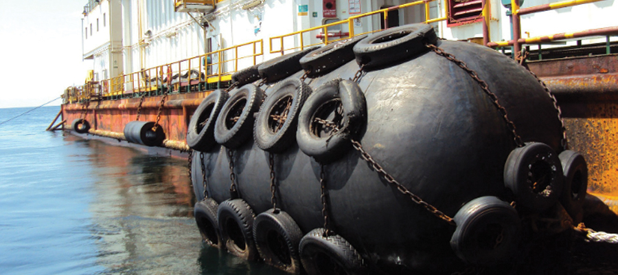
A fender can be defined as a bumper that absorbs kinetic energy during contact between a berthing vessel and the harbor jetty. Fenders are used to protect vessels and jetties from destruction during parking in the harbor and are produced from rubber or other elastomers. The main function of the rubber fender is to effectively absorb the kinetic energy and lower reaction force.
The main goal of the project presented in this article was to perform a structural analysis with SimScale to check the contact between the rubber fender and a yacht hull. The vessel has a speed of 1,5m/s and pushes against the fender connected to the jetty.
Simulation Steps
The geometry of the model was created with CAD software and imported into the SimScale CAE platform, where the meshing and definition of the model and material properties were done. This was performed easily as SimScale supports several geometry formats: STEP, IGES, BREP, STL.
Besides the user-friendly interface which makes the simulation process faster, the documentation and public projects library definitely help with answering questions and learning. Experience with other commercial software enables a very smooth adaptation to SimScale.
SimScale divides the analysis into three parts: mesh generator, simulation designer, and post-processor:
- Mesh generator – the user uploads the CAD design ready to be meshed
- Simulation designer – the user chooses the solver and analysis type, defines the domain and contact type, and chooses contact areas. This step allows the definition of the material and assigns it to the geometry. The basic information used in the simulation such as boundary conditions and initial conditions are defined in this part. After this, the user runs the analysis.
- Post-processor – in the last step, the user is able to review the completed analysis and plot the required results. It is possible to plot the solver information such as the number of iterations and residuals. SimScale allows plotting simulation fields such as displacement and stress fields.
SimScale’s CEO David Heiny tests the capabilities of the platform to solve a real-life engineering problem. Fill in the form and watch this free webinar to learn more!
Structural Analysis of the Fender
The model was built from three parts: part of the vessel(1), fender(2), and jetty(3).

For this situation, some analytical calculations should be performed in order to select the type of fender. Below are the analytical calculations of the fender with a picture of the vessel used for calculations.
The first step in the structural analysis is to find the stiffness of the fender and its energy absorption. For this, it is necessary to analyze it with a load of 1N. Thereafter the fender’s deflection needs to be checked, which is shown in the picture below.

The stiffness of the fender can be calculated as follows:
![]()
A contact analysis between the fender and vessel was done as well:
For numerical calculations, it is necessary to make some assumptions. Because only a part of the vessel is modeled, the density of the material needs to be changed to keep a correct mass of the structure.

The next step is meshing the structure. For model discretization, 3D elements were used. The meshed model can be seen below:

The model was built from three elements and in this case, it is necessary to use contact definition for the connected parts. Contact between fender and jetty is defined as a bonded contact. The connection between vessel and fender is defined as a physical connection with no friction.
The model was created with three types of material: fender – rubber, jetty – concrete, and vessel – steel (density 7,81 t/m3).
The vessel’s velocity is defined as an initial condition with a value of 1,5m/s. The model is constrained on the sides of the jetty as fixed.
The next step of the analysis is to plot the stress fields, displacements, and deformation fields.

To check the calculations, analytical calculations were prepared.
For verification of the results, the kinetic energy between results of the numerical calculations and the kinetic energy received from analytical formulas was compared.
Numerical calculations:
![]()
Analytical calculations can be found below:

The difference between the two results was 16%.
Conclusion
During this structural analysis, a self-modeled shape of the fender was used. There was no specific information about energy absorption. Normally, fender producers will use specialized laboratories to find out more about the product’s properties, but most of the time, this type of solution is quite expensive.
In this analysis, SimScale was used as a lab to find out more about the shape and its parameters. Deformation results of the fender gave possibilities to check energy absorption of the structure. By using numerical analysis (CAE), engineers can analyze and optimize many shapes before the final one will be chosen and tested with a physical prototype.
This simulation was performed by Pawel Dereszewski from FEM NEWS.


